Class diagram
A class diagram describes the structure of an object-oriented system by showing the system’s classes, their attributes, and the relationships among the classes.
Members
The UML provide mechanisms to represent class members, such as attributes and methods, and additional information about them.
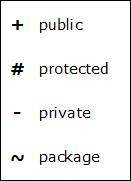
Visibility
To specify the visibility of a class member (attributes and methods) there are the following notations that must be placed before the member’s name.
Scope
The UML specifies two types of scope for members: instance and classifier. In the case of instance members, the scope is a specific instance. For attributes, it means that its value can vary between instances. For methods, it means that its invocation affects the instance state, in other words, affects the instance attributes. Otherwise, in the classifier member, the scope is the class. For attributes, it means that its value is equal for all instances. For methods, it means that its invocation do not affect the instance state. Classifier members are commonly recognized as “static” in many programming languages. To indicate that a member has the classifier scope, its name must be underlined. Otherwise, as default, the instance scope is considered.
Class diagrams are widely used to describe the types of objects in a system and their relationships. Class diagrams model class structure and contents using design elements such as classes, packages and objects. Class diagrams describe three different perspectives when designing a system, conceptual, specification, and implementation.
UML Class Notation
Classes are composed of three things: a name, attribute(s), and operation(s). Below is an example of a class.
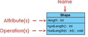
Figure 1: A Sample Class
Class diagrams are some of the most difficult UML diagrams to draw. To draw detailed and useful diagrams a person would have to study UML and Object-oriented design principles for a long time.
When designing classes we have to consider what attributes and operations it will have. Then we try to determine how instances of the classes will interact with each other. These are the very first steps of many in developing a class diagram. However, using just these basic techniques one can develop a complete view of the software system.
Relationship Types
A relationship is a general term covering the specific types of logical connections found on class and objects diagrams. UML shows the following relationships:
1. Instance level relationships
2. Class level relationships
1. Instance Level Relationships
Links and associations are the means for building the relationships among the objects and classes. Links and associations, both are quite same feature but links establishing among the objects (instance) and association establishing among the class.
Link
A Link is the basic relationship among objects. It is represented as a line connecting two or more object boxes. It can be shown on an object diagram. A link is an instance of an association.
I. Association
An Association represents structural relationship between objects of different classes; it represents connection between instances of two or more classes that exist for some duration. In other words: “Association represents the static relationships shared among the objects of different classes where all objects have their own life-cycle and there is no owner.”
Degree of Association
The degree of association defines the number of classes connected by association. The most common and frequent associations are based on the degree:
(i) Unary association (degree of one)
(ii) Binary association (degree of two)
(iii) Ternary association (degree of three)
(iv) Quaternary association (degree of four)
(v) N-ary Associations
Binary associations (with two ends) are normally represented as a line, with each end connected to a class box.
An association can be named, and the ends of an association can be adorned with role names, ownership indicators, multiplicity, visibility, and other properties. Associations can only be shown on class diagrams.
Example: Multiple objects of Student class can associate with a single object of Department class and single Student object can associate with multiple objects of Department, but there is no ownership between the objects and both have their own life-cycle. Both can be created and deleted independently. See Figure 2 below.
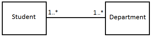
Figure 2: Class diagram example of association between two classes
Multiplicity
The association relationship indicates that (at least) one of the two related classes makes reference to the other. In contrast with the generalization relationship, this is most easily understood through the phrase ‘A has a B’ (a mother cat has kittens, kittens have a mother cat).
The UML representation of an association is a line with an optional arrowhead indicating the role of the object(s) in the relationship, and an optional notation at each end indicating the multiplicity of instances of that entity (the number of objects that participate in the association). Common multiplicities are:
0..1 | No instances, or one instance (optional, may) |
1 | Exactly one instance |
0..* or * | Zero or more instances |
1..* | One or more instances (at least one) |
II. Aggregation
An Aggregation or “has-a” relationship is a variant of the association; aggregation is more specific than association. It is an association that represents a part-whole relationship.
As a type of association, an aggregation can be named and have the same adornments that an association can. However, an aggregation may not involve more than two classes.
Aggregation can occur when a class is a collection or container of other classes, but where the contained classes do not have a strong life-cycle dependency on the container—essentially, if the container is destroyed, its contents are not. In UML, it is graphically represented as a clear diamond shape on the containing class end of the tree of lines that connect contained class(es) to the containing class.
Example: Multiple “Employee” objects can belong to single “Company” object, but if we delete the “Company” object , “Employee” object will not be destroyed. See Figure 3 below.
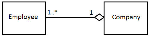
Figure 3: Class diagram showing Aggregation between two classes
III. Composition
A Composition is a stronger variant of the “has-a” or association relationship; composition is more specific than aggregation. It is represented with a solid diamond shape. It is also called the “owns-a” relationship.
Composition usually has a strong life-cycle dependency between instances of the container class and instances of the contained class(es): If the container is destroyed, normally every instance that it contains is destroyed as well. Note that a part can (where allowed) be removed from a composite before the composite is deleted, and thus not be deleted as part of the composite.
The UML graphical representation of a composition relationship is a filled diamond shape on the containing class end of the tree of lines that connect contained class (es) to the containing class.
Example: A “House” object can contain multiple “Room” objects considering there is no independent life for “Room” and any “Room” can not belong to two different “House” objects. If we delete the House object, Room object(s) will also be automatically deleted. See Figure 4 below.
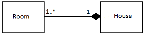
Figure 4: Class diagram showing Composition between two classes
Association vs. Aggregation vs. Composition
- Association is the most general (m : n) relationship. Aggregation is a stronger relationship where one is a part of the other. Composition is even stronger than aggregation, ties the life cycle of the part and the whole together.
- Association relationship can be reflexive (objects can have relation to itself), but aggregation cannot be reflexive. Moreover, aggregation is anti-symmetric (If B is a part of A, A can not be a part of B).
- Composition has the property of exclusive aggregation i.e. an object can be a part of only one composite at a time. For example, a Frame belongs to exactly one Window whereas in simple aggregation, a part may be shared by several objects. For example, a Wall may be a part of one or more Room objects.
- In addition, in composition, the whole has the responsibility for the disposition of all its parts, i.e. for their creation and destruction. In general, the lifetime of parts and composite coincides. Parts with non-fixed multiplicity may be created after composite itself. Parts might be explicitly removed before the death of the composite
For example, when a Frame is created, it has to be attached to an enclosing Window. Similarly, when the Window is destroyed, it must in turn destroy its Frame parts.
So in summary, we can say that aggregation is a special kind of an association and composition is a special kind of an aggregation (Association -> Aggregation -> Composition).
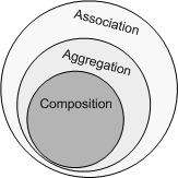
Figure 5: Association, Aggregation and Composition
2. Class Level Relationships
Class level relationships are of two types: generalization and realization. These topics are discussed below.
I. Generalization (or Inheritance)
The Generalization relationship indicates that one of the two related classes (the sub-type) is considered to be a specialized form of the other (the super-type) and super-type is considered as Generalization of sub-type. In practice, this means that any instance of the sub-type is also an instance of the super-type. An exemplary tree of generalizations of this form is found in binomial nomenclature: human beings are a sub-type of simian, which are a sub-type of mammal, and so on. The relationship is most easily understood by the phrase ‘A is a B’ (a human is a mammal, a mammal is an animal).
The UML graphical representation of a Generalization is a hollow triangle shape on the super-type end of the line (or tree of lines) that connects it to one or more sub-types. The generalization relationship is also known as the inheritance or “is-a“ relationship.
The super-type in the generalization relationship is also known as the “parent”, superclass, base class, or base type. The sub-type in the generalization relationship is also known as the “child”, subclass, derived class, derived type, inheriting class, or inheriting type.
Generalization can only be shown on class diagrams and on Use case diagrams.
The figure below shows an example of inheritance hierarchy using a class diagram. SubClass1 and SubClass2 are derived from SuperClass. The relationship is displayed as a solid line with a hollow arrowhead that points from the child element to the parent element.

The features of generalization are given below:
- It represents an “is-a” relationship.
- An abstract class name is shown in italics.
- SubClass1 and SubClass2 are specializations of SuperClass.
Note that this relationship bears no resemblance to the biological parent/child relationship: the use of these terms is extremely common, but can be misleading.
Generalization-Specialization relationship:
- A is a type of B
- E. g. “an oak is a type of tree”, “an automobile is a type of vehicle”
II. Realization
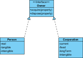
In UML modeling, a realization relationship is a relationship between two model elements, in which one model element (the client) realizes the behavior that the other model element (the supplier) specifies. A realization is displayed in the diagram editor as a dashed line with an unfilled arrowhead towards the supplier. Realizations can only be shown on class diagrams.
A realization is a relationship between classes, interfaces, components, and packages that connects a client element with a supplier element. A realization relationship between classes and interfaces and between components and interfaces shows that the class realizes the operations offered by the interface.
It is basically a relationship between the blueprint (or design) class and the object containing its respective implementation level details. This object is said to realize the blueprint (or design) class. In other words, we can understand this as the relationship between the interface and the implementing class.
For example, in Java, the Owner interface might specify methods for acquiring property and disposing of property. The Person and Corporation classes need to implement these methods, possibly in very different ways.
IS-A vs. HAS-A
The IS-A (i.e. Inheritance) relationship is basically a generalization-specialization relationship in OOP. A human being is a kind of mammal. Mammal is a kind of animal. It is a relationship between a special class and a general class. The special class inherits the properties of general class. On the other hand, in a HAS-A (i.e. Aggregation) relationship, objects of one class are part of objects of another class. For example, object of Company class has object(s) of Employee class. So, Employee class is a part of Company class (i.e. whole-part relationship).