Communication diagram / Collaboration diagram
Communication diagrams / Collaboration diagrams are also relatively easy to draw. They show the relationship between objects and the order of messages passed between them. The objects are listed as icons and arrows indicate the messages being passed between them. The numbers next to the messages are called sequence numbers. As the name suggests, they show the sequence of the messages as they are passed between the objects. There are many acceptable sequence numbering schemes in UML. A simple 1, 2, 3… format can be used, as the example below shows, or for more detailed and complex diagrams a 1, 1.1, 1.2, 1.2.1… scheme can be used.
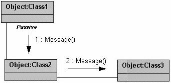
Figure 1: A Sample Collaboration Diagram
The example below shows a simple collaboration diagram for the placing an order use case. This time the names of the objects appear after the colon, such as: Order Entry Window following the objectName: className naming convention.
This time the class name is shown to demonstrate that all of objects of that class will behave the same way.
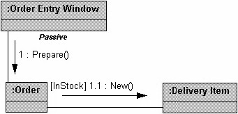
Figure 2: Example Collaboration Diagram