Component diagram
Component diagrams show the software components of a system and how they are related to each other. These relationships are called dependencies.
Component diagrams are basically used to model the physical aspects of a system. Physical aspects are the elements such as executables, libraries, files, documents, etc. which reside in a node.
Many times the deployment and component diagrams are combined into one physical diagram. A combined deployment and component diagram combines the features of both diagrams into one diagram.
The component diagram contains components and dependencies. Components represent the physical packaging of a module of code. The dependencies between the components show how changes made to one component may affect the other components in the system. Dependencies in a component diagram are represented by a dashed line between two or more components. Component diagrams can also show the interfaces used by the components to communicate to each other.
The combined deployment and component diagram below gives a high level physical description of the completed system. The diagram shows two nodes which represent two machines communicating through TCP/IP. Component2 is dependent on component1, so changes to component2 could affect component1. The diagram also depicts component3 interfacing with component1.
This diagram below gives a quick overall view of the entire system.
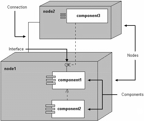
Figure 1: The combined deployment and component diagram
Objective of Component diagrams
Component diagram is a special type of diagram in UML. The objective is also different from all other diagrams discussed so far. It does not describe the functionality of the system but it describes the components used to make those functionalities.
Thus from that point of view, component diagrams are used to visualize the physical components in a system. These components are libraries, packages, files, etc.
Component diagrams can also be described as a static implementation view of a system. Static implementation represents the organization of the components at a particular moment.
A single component diagram cannot represent the entire system but a collection of diagrams is used to represent the whole.
The purpose of the component diagram can be summarized as —
Visualize the components of a system.
Construct executables by using forward and reverse engineering.
Describe the organization and relationships of the components.