UML Modeling
Modeling is an essential part of large software projects. Use of a model, in a software project ensures scalability, robustness, security, extensibility, and other features. A robust design always ensures smooth development. Surveys show that large software projects have a huge probability of failure – in fact, it’s more likely that a large software application will fail to meet all of its requirements on time and on budget than that it will succeed. Modeling is thus the only way to visualize out design and check it against requirements before any coding begins.
It is very important to distinguish between the UML model and the set of diagrams of a system. A diagram is a partial graphical representation of a system’s model. The model also contains a “semantic backplane” — documentation such as written use cases that drive the model elements and diagrams.
UML diagrams represent two different views of a system model:
♦ Static (or structural) view: Emphasizes the static structure of the system using objects, attributes, operations and relationships. The structural view includes class diagrams and composite structure diagrams.
♦ Dynamic (or behavioral) view: Emphasizes the dynamic behavior of the system by showing collaborations among objects and changes to the internal states of objects. This view includes sequence diagrams, activity diagrams and state machine diagrams.
The above classification leads to the two different types of UML models, namely, Static Model (with respect to structural view) and Dynamic Model (with respect to behavioral view). UML models can be exchanged among UML tools by using the XML Metadata Interchange (XMI) format.
UML Diagrams Overview
UML is a way of visualizing a software program using a collection of diagrams. The notation has evolved from the work of Grady Booch, James Rumbaugh, Ivar Jacobson, and the Rational Software Corporation to be used for object-oriented design, but it has since been extended to cover a wider variety of software engineering projects. Today, UML is accepted by the Object Management Group (OMG) as the standard for modeling software development.
UML 2.x has 13 types of diagrams divided into three categories. Six diagram types represent the structure application; seven represent general types of behavior, including four that represent different aspects of interactions. These diagrams can be categorized hierarchically as shown in the following class diagram:
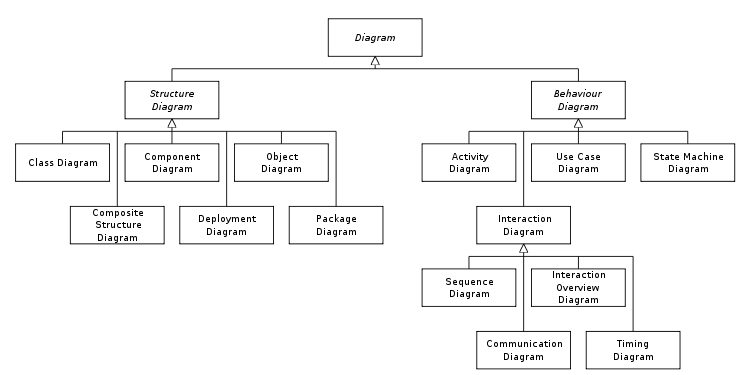
Figure 1: Hierarchy of UML diagrams
UML does not restrict UML element types to a certain diagram type. In general, every UML element may appear on almost all types of diagrams. This flexibility has been partially restricted in UML 2.x. In keeping with the tradition of engineering drawings, a comment or note explaining usage, constraint, or intent is always allowed in a UML diagram.
Need for UML
As the strategic value of software increases for many companies, the industry looks for techniques to automate the production of software and to improve quality and reduce cost and time-to-market. These techniques include component technology, visual programming, patterns and frameworks. Businesses also seek techniques to manage the complexity of systems as they increase in scope and scale. In particular, they recognize the need to solve recurring architectural problems, such as physical distribution, concurrency, replication, security, load balancing and fault tolerance. Additionally, the development for the World Wide Web, while making some things simpler, has exacerbated these architectural problems. UML was designed to respond to these needs.