Deployment diagram
Deployment diagrams show the physical relationship between hardware and software in a system. They are used to describe the static deployment view of a system.
The deployment diagram contains nodes and connections. A node usually represents a piece of hardware in the system. A connection depicts the communication path used by the hardware to communicate and usually indicates a method such as TCP/IP.
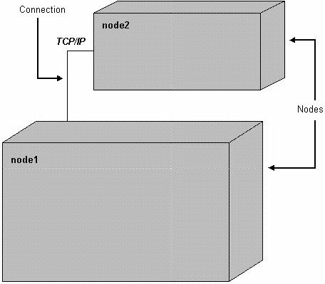
Figure 1: A Sample Deployment Diagram
Objective of Deployment diagrams
Deployment diagrams are used for describing the hardware components, where software components are deployed. Component diagrams and deployment diagrams are closely related.
Component diagrams are used to describe the components and deployment diagrams shows how they are deployed in hardware.
UML is mainly designed to focus on the software artifacts of a system. However, these two diagrams are special diagrams used to focus on software and hardware components.
Most of the UML diagrams are used to handle logical components but deployment diagrams are made to focus on the hardware topology of a system. Deployment diagrams are used by the system engineers.
The purpose of deployment diagrams can be described as −
Visualize the hardware topology of a system.
Describe the hardware components used to deploy software components.
Describe the runtime processing nodes.