Use Case diagram
In software engineering, a Use Case Diagram is a type of Behavioral UML diagram defined by and created from a Use-case analysis. Its purpose is to present a graphical overview of the functionality provided by a system in terms of actors, their goals (represented as use cases), and any dependencies between those use cases.
Use Case diagrams are formally included in two modeling languages defined by the OMG. Both the UML and SysML standards define a graphical notation for modeling use cases with diagrams. One complaint about the standards has been that they do not define a format for describing these use cases. Generally, both graphical notation and descriptions are important as they document the use case, showing the purpose for which an actor uses a system.
A use case is a set of scenarios that describing an interaction between a user and a system. A use case diagram displays the relationship among actors and use cases. The two main components of a use case diagram are use cases and actors.
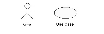
Figure 1: Actor and Use Case
An actor represents a user or another system that will interact with the system we are modeling. A use case is an external view of the system that represents some action the user might perform in order to complete a task. The main purpose of a use case diagram is to show what system functions are performed for which actors. Roles of the actors in the system can be depicted.
When to Use: Use Cases Diagrams
Use cases are used in almost every project. They are helpful in exposing requirements and planning the project. During the initial stage of a project most use cases should be defined, but as the project continues more might become visible.
How to Draw: Use Cases Diagrams
Use cases are a relatively easy UML diagram to draw, but this is a very simplified example. This example is only meant as an introduction to the UML and use cases. We start by listing a sequence of steps that a user might take in order to complete an action.
For example a user placing an order with a sales company might follow these steps.
- Browse catalog and select items.
- Call sales representative.
- Supply shipping information.
- Supply payment information.
- Receive conformation number from salesperson.
These steps would generate this simple use case diagram:
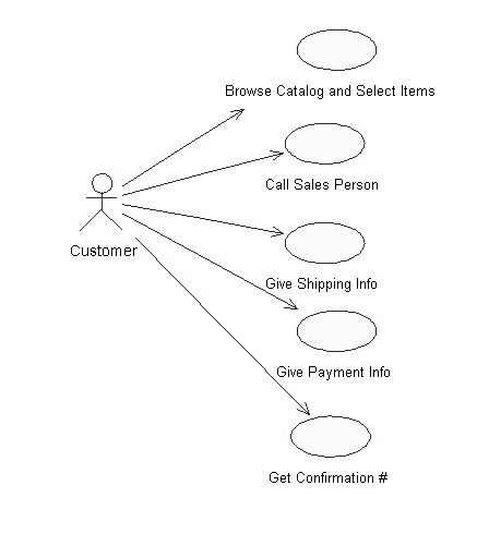
Figure 2: A Simple Use Case Diagram
This example shows the customer as an actor because the customer is using the ordering system. The diagram takes the simple steps listed above and shows them as actions the customer might perform. The salesperson could also be included in this use case diagram because the salesperson is also interacting with the ordering system.
From this simple diagram the requirements of the ordering system can easily be derived. The system will need to be able to perform actions for all of the use cases listed. As the project progresses other use cases might appear. The customer might have a need to add an item to an order that has already been placed. This diagram can easily be expanded until a complete description of the ordering system is derived capturing all of the requirements that the system will need to perform.
Use Case Relationships:
Three relationships among use cases are used often in practice.
(a) Include
In one form of interaction, a given use case may include another. “Include is a Directed Relationship between two use cases, implying that the behavior of the included use case is inserted into the behavior of the including use case”.
The first use case often depends on the outcome of the included use case. This is useful for extracting truly common behaviors from multiple use cases into a single description. The notation is a dashed arrow from the including to the included use case, with the label “«include»”.
This usage resembles a macro expansion where the included use case behavior is placed inline in the base use case behavior. There are no parameters or return values. To specify the location in a flow of events in which the base use case includes the behavior of another, we simply write include followed by the name of use case we want to include, as in the following flow for track order.
(b) Extend
In another form of interaction, a given use case (the extension) may extend another. This relationship indicates that the behavior of the extension use case may be inserted in the extended use case under some conditions. The notation is a dashed arrow from the extension to the extended use case, with the label “«extend»”. Notes or constraints may be associated with this relationship to illustrate the conditions under which this behaviour will be executed.
Modelers use the «extend» relationship to indicate use cases that are “optional” to the base use case. Depending on the modeler’s approach “optional” may mean “potentially not executed with the base use case” or it may mean “not required to achieve the base use case goal.”
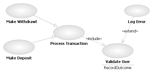
Figure 3: Use case relationships using <> and <>
(c) Generalization
In the third form of relationship among use cases, a generalization/specialization relationship exists. A given use case may be a specialized form of an existing use case. The notation is a solid line ending in a hollow triangle drawn from the specialized to the more general use case.
This resembles the object-oriented concept of sub-classing, in practice it can be both useful and effective to factor out common behaviors, constraints and assumptions to the general use case, describe them once, and deal with it in the same way, except for the details in the specialized cases.
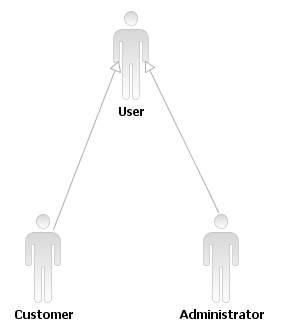
Figure 4: Generalization/Specialization relationship
Another Example
The use case diagram shows the position or context of the use case among other use cases. As an organizing mechanism, a set of consistent, coherent use cases promotes a useful picture of system behavior, a common understanding between the customer/owner/user and the development team.
This diagram below describes the functionality of a simple Restaurant Management System. Use cases are represented by ovals and the actors are represented by stick figures. The Customer actor can Order Food (and optionally Order Juice), Eat Food (and optionally Drink Juice), Pay for Food (and optionally Pay for Juice).
Multiple actors participate in some of the use cases. In such cases, the label on the association between the actor and the use case throws some light on the actor’s contribution to the use case. The box defines the boundaries of the Restaurant Management System, i.e., the use cases shown are part of the system being modeled, the actors are not.
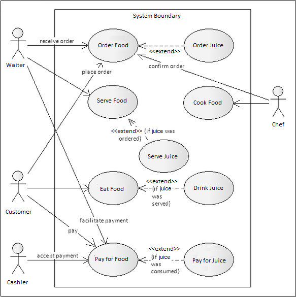
Figure 5: A Simple Restaurant Management System
In the above Use Case Diagram the “actors” are —
Waiter, Customer, Cashier, and Chef.
The “use cases” are –
Order Food, Serve Food, Eat Food, Pay for Food, Order Juice, Cook Food, Serve Juice, Drink Juice, and Pay for Juice.