Sequence diagram
Sequence diagrams demonstrate the behavior of objects in a use case by describing the objects and the messages they pass. The diagrams are read left to right and descending. The example below shows an object of class 1 start the behavior by sending a message to an object of class 2. Messages pass between the different objects until the object of class 1 receives the final message.
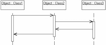
Figure 1: A Simple Sequence Diagram
Below is a slightly more complex example. The vertical rectangles denote the objects activation while the vertical dashed lines represent the life of the object. The vertical rectangles represent when a particular object has control. The represents when the object is destroyed. This diagram also shows conditions for messages to be sent to other object. The condition is listed between brackets next to the message. For example, a [condition] has to be met before the object of class 2 can send a message() to the object of class 3.
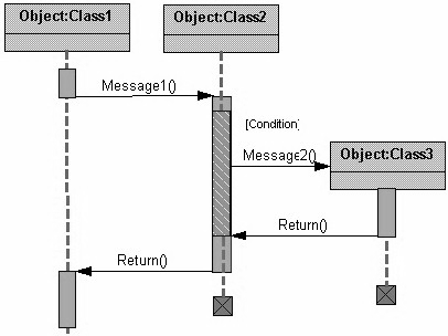
Figure 2: A Complex Sequence Diagram
The next diagram shows the beginning of a sequence diagram for placing an order. The object an Order Entry Window is created and sends a message to an Order object to prepare the order. Notice the names of the objects are followed by a colon. The names of the classes the objects belong to do not have to be listed. However the colon is required to denote that it is the name of an object following the objectName: className naming system. Next the Order object checks to see if the item is in stock and if the [InStock] condition is met it sends a message to create a new Delivery Item object.
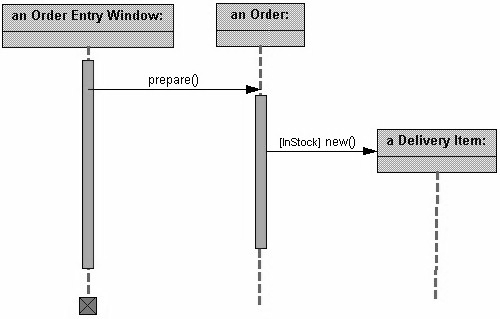
Figure 3: A Sample Sequence Diagram
The next diagram adds another conditional message to the Order object. If the item is [OutOfStock] it sends a message back to the Order Entry Window object stating that the object is out of stack.
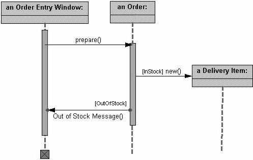
Figure 4: A Sequence Diagram with conditional message
This above diagram shows the sequence that messages are passed between objects to complete a use case for ordering an item.