UML Extensibility Mechanisms
Object-oriented analysis and design is the method that leads us to object oriented decomposition. They can be defined as follows.
There is an important need for organizations to evolve in today’s market. This has led to a knowledge revolution, which enables organizations to be agile and responsive by strategically capturing, communicating and leveraging intellectual assets. Object orientation and component-based development are the backbone of this revolution and it is the UML that brings these together into an essential foundation for evolution. But it is the UML extension mechanisms that take this a step further and make it possible for an organization to truly evolve in an agile and responsive fashion, by strategically capturing, communicating and leveraging intellectual assets.
The UML is a general-purpose, tool supported, and standardized modeling language that is used in order to specify, visualize, construct and document all the elements of a wide range of system intensive processes. It promotes a use case driven, architecture-centric, iterative and incremental process, which is object oriented and component-based. The UML is broadly applicable to different types of systems, domains, methods and processes, which is why it is such a popular and broadly used language.
However, even though the UML is very well-defined, there might be situations in which we might find ourselves wanting to extend the language in some controlled way to tailor it to our specific problem domain in order to simplify the communication of our objective. This is where the UML extension mechanisms come in.
There exist four common mechanisms that can be used consistently throughout the language – namely specifications, common divisions, adornments, and extensibility mechanisms – which we are going to deal with here; however, the main focus of this work will be on the latter of these four, i.e. the extensibility mechanisms.
1. Specifications
The first extension mechanism that was mentioned earlier is called specifications. This is a very easy term to grasp as we all know what a specification means in our everyday language. In the UML it is just as simple. By using a specification, we are basically specifying something in a bit more detail so that the role and meaning of the term being specified is presented to us in a more clear and concise manner. For example, we can give a class a rich specification by defining a full set of attributes, operations, full signatures, and behaviors. We will then have a clearer notion of what the capabilities and limitations of that class are. Specifications can be included in the class, or specified separately.
2. Common Divisions
This is the second extension mechanism that is provided to us by the UML. Common divisions are used in order to distinguish between two things that might appear to be quite similar, or closely related to one another. There exist two main common divisions: abstraction vs. manifestation and interface vs. implementation.
In the former, we mainly talk about the distinction between a class and an object, where the class is an abstraction and the object is a clear manifestation of that class. Most UML building blocks have this kind of class/object distinction, e.g. use case, use case instance etc.
In the second common division – interface vs. implementation – we say that an interface declares some kind of contract, or agreement, whereas an implementation represents one concrete realization of that contract. The implementation is then responsible for carrying out the interface.
3. Adornments
Adornments are textual or graphical items, which can be added to the basic notation of a UML building block in order to visualize some details from that element’s specification. For example, let us consider association, which in its most simple notation consists of one single line. Now, this can be adorned with some additional details, such as the role and the multiplicity of each end (see Figure 1).
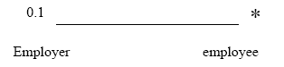
Figure 1: Association Example
One of the most important kinds of adornments is a note. This is a graphical symbol, which is used for adding some comments or constraints to an element (or a collection of elements) to help clarify the models that are being created. We may use notes in order to attach some additional information to our model, such as an explanation, a requirement, or just simply an observation (see Figure 2).
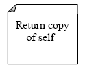
Figure 2: A Sample Note
It is worth mentioning that a note carries no semantic impact, i.e. the content of a note does not in any way change the meaning or significance of the model to which it is attached.
4. Extensibility Mechanisms
The extensibility mechanisms allow us to customize and extend the UML by adding new building blocks, creating new properties, and specifying new semantics in order to make the language suitable for our specific problem domain. There are three common extensibility mechanisms that are defined by the UML: stereotypes, tagged values, and constraints.
(a) Stereotypes
Stereotypes allow us to extend the vocabulary of the UML so that we can create new model elements, derived from existing ones, but that have specific properties that are suitable for our problem domain. They are used for classifying or marking the UML building blocks in order to introduce new building blocks that speak the language of our domain and that look like primitive, or basic, model elements.
For example, when modelling a network we might need to have symbols for representing routers and hubs. By using stereotyped nodes we can make these things appear as primitive building blocks.
As another example, let us consider exception classes in Java or C++, which we might sometimes have to model. Ideally we would only want to allow them to be thrown and caught, nothing else. Now, by marking them with a suitable stereotype we can make these classes into first class citizens in our model; in other words, we make them appear as basic building blocks.
Graphically, a stereotype is rendered as a name enclosed by guillemets (‘<< >>’) and placed above the name of another element (see Figure 3).
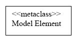
Figure 3: Named Stereotype
Stereotypes also allow us to introduce new graphical symbols for providing visual cues to the models that speak the vocabulary of our specific domain (see Figure 4).
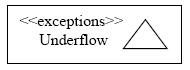
Figure 4: Named Stereotype with visual cues
Alternatively, we can render the stereotyped element by using a new icon associated with that stereotype (see Figure 5).
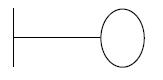
Figure 5: Stereotyped elements as Icon
(b) Tagged Values
Tagged values are properties for specifying keyword-value pairs of model elements, where the keywords are attributes. They allow us to extend the properties of a UML building block so that we create new information in the specification of that element. Tagged values can be defined for existing model elements, or for individual stereotypes, so that everything with that stereotype has that tagged value. It is important to mention that a tagged value is not equal to a class attribute. Instead, we can regard a tagged value as being a metadata, since its value applies to the element itself and not to its instances.
One of the most common uses of a tagged value is to specify properties that are relevant to code generation or configuration management. So, for example, we can make use of a tagged value in order to specify the programming language to which we map a particular class, or we can use it to denote the author and the version of a component.
As another example of where tagged values can be useful, consider the release team of a project, which is responsible for assembling, testing, and deploying releases. In such a case it might be feasible to keep track of the version number and test results for each main subsystem, and so one way of adding this information to the models is to use tagged values.
Graphically, a tagged value is rendered as a string enclosed by brackets, which is placed below the name of another model element. The string consists of a name (the
tag), a separator (the symbol =), and a value (of the tag) (see Figure 6).
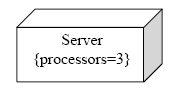
Figure 6: Tagged Value Example
(c) Constraints
Constraints are properties for specifying semantics and/or conditions that must be held true at all times for the elements of a model. They allow us to extend the semantics of a UML building block by adding new rules, or modifying existing ones.
For example, when modeling hard real time systems it could be useful to adorn the models with some additional information, such as time budgets and deadlines. By making use of constraints these timing requirements can easily be captured.
Graphically, a constraint is rendered as a string enclosed by brackets, which is placed near the associated element(s), or connected to the element(s) by dependency relationships. This notation can also be used to adorn a model element’s basic notation, in order to visualize parts of an element’s specification that have no graphical cue.
For example, we can use constraint notation to provide some properties of associations, such as order and changeability (see Figure 7).
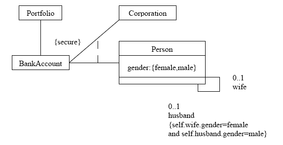
Figure 7: Formal Constraint using Object Constraint Language (OCL)
The Object Constraint Language (OCL) is a declarative language for describing rules that apply to UML models developed at IBM and now part of the UML standard. Initially, OCL was only a formal specification language extension to UML. OCL may now be used with any Meta-Object Facility (MOF) Object Management Group (OMG) meta-model, including UML.
OCL is a precise text language that provides constraint and object query expressions on any MOF model or meta-model that cannot otherwise be expressed by diagrammatic notation. OCL is a key component of the new OMG standard recommendation for transforming models, the Queries/Views/Transformations (QVT) specification.
SUMMARY
» UML is just syntax. It says nothing about how to create a model.
» UML is well documented but little understood.
» It was developed by Booch, Rumbaugh and Jacobson at Rational Software.
» UML 2.x specifies 13 different diagrams. Not all are used in practice.
» UML can be extended through the use of stereotypes.
» A use case diagram shows the functionality of the system from the outside-in.
» Class diagrams show the static structure of the systems.
» Sequence diagrams show potential interactions between objects in the system in the order in which they normally occur.
» Collaboration diagrams also show interaction between objects, but emphasize the structure required to support them.
» State charts are a class-centric view of system functionality.
» An activity diagram is a general purpose flowchart.
» Component diagrams show the types of software components in the system, their interfaces and dependencies.
» Deployment diagrams show the computing nodes in the system, their communication links, the components that run on them and their dependencies.